
Measuring water level is fundamental goal of WLS experiment, hence its code-name (Water Level Station). Early summer 2014 hardware and software system had enough base services to make addition of entry-level pluviometer easy. Prior to PCB redesing for chinese factory I blueprinted and bread-boarded extra input circuitry in couple hours. Software part took me couple more days and my balcony-mounted station started measuring precipitation mid summer season.
Rain gauges deployment was necessary from the very beginning – possibility of correlation intense rainfalls with water levels changes (in long term scale) could be valuable input for flood prediction models. At the beginning however neither me nor my brother was sure I can develop a hardware system from scratch. With working WLS prototype I decided to review pluviometer feature before finalizing shrinked PCB design ready-made for professional production.
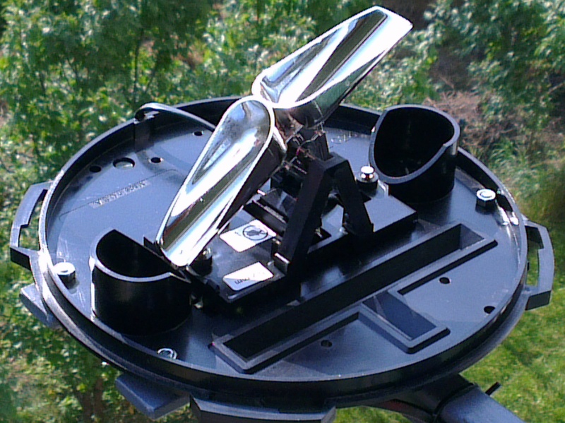
Davis 7852M rain gauge
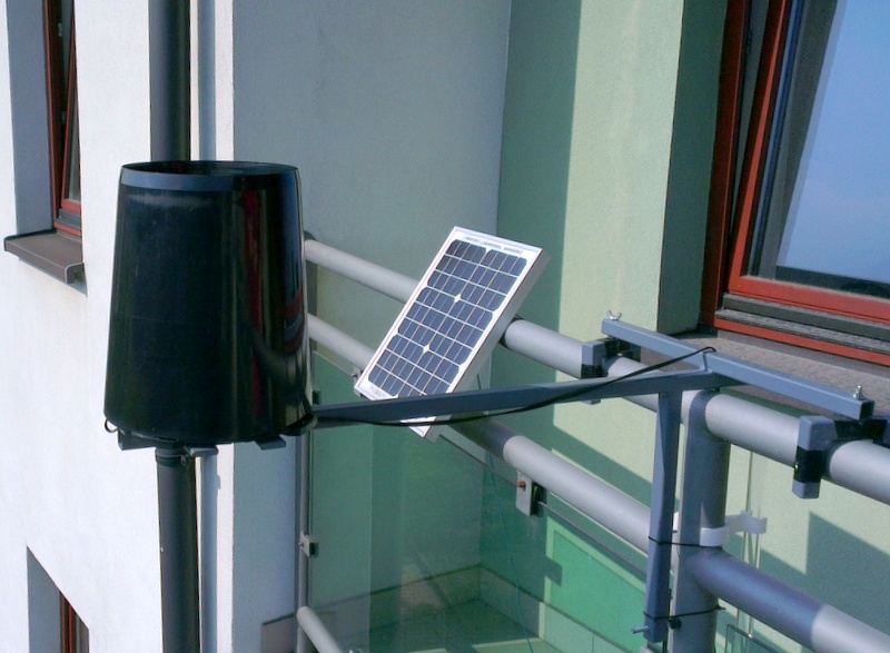
Station “balcony-1”
Brief research attracted me to Davis 7852M tipping bucket rain gauge. This device cannot be compared with high-precission laser beam or acoustic disdrometers for sure. It suffers from all problems typical for tipping-bucket gauges: low sensitivity for small rains (due to evaporation), increasing measurement errors with rain intensity (due to spilling water) or lack of winter measurements due to low-power and unability to melt snow.
Even such basic capability sounds fantastic because, for flood prone highland’s river system in my country, existing data granularity is not enough. Neither for accurate predictions nor scientific research. It is fascinating that on one hand administration reduced number of gauging stations roughly by 300 in 90’s (by 20-30%, depending on source), on the other hand they claims that measurement network meets World Meterological Organization guidelines. Growing the network is intuitive and fundamental, instead, government created consortium that builds super-duper computer systems to analyse and make predictions on existing foundation. No changes were made to improve gauging basis, yet hazard and flood risk maps are created from inaccurate, highly extrapolated predictions, without real data behind. Welcome to Euro-sowchoz management style…
Hardware extension for WLS rain gauge was trivial indeed. Rain gauge works as normally-open reed switch being shorted briefly by magnetic field when bucket is tipped. Each pulse means 0.2mm of rainfall and must be simply counted. Reed switch is isolated with optocoupler: shorted reed powers up photodiode that make photo-transistor conducting and shorting pull-up on MCU pin.
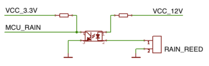
Input opto-coupler
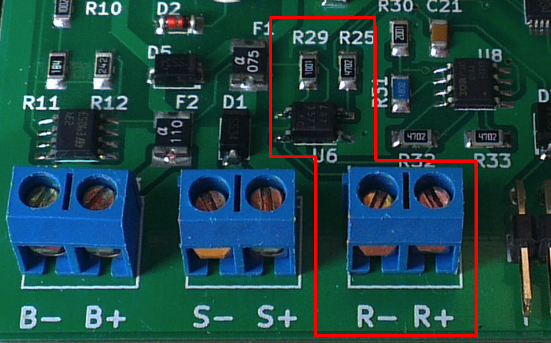
Gauge singal input
Software interface was closed in half-screen of source code but I spent many hours refactor station-server communication protocol that now supports local file-system queue for variety of messages sent over the network. Pulse inversion on optocoupler is designed by purpose. When pulse comes MCU is awaken from deep sleep; holding pin low is the only way to asynchronously wake Atmega128 up and jump to external interrupt. ISR handler with debouncing is just increasing counting semaphore; FreeRTOS task is processing pulses aggregating them with one-minute resolution to get flash rainfall captured. Final result is that rainfall data is collected and for dozen weeks now measures rain next to my balcony. Once station with pluviometer is deployed it is just a matter of configuration to switch-on extra feature without any other modification.
See also other related articles:
[posts_by_tag tag=”WLS”]


