
So you got SIM900A, cheaper version of SIM900 with the same pinout/functions and 2-band instead of 4-band GSM radio, just to stumble on logging to network. While its great for Asian GSM infrastructure in different places in the world you will just get “PH-NET PIN” response meaning its locked for current network. I found that flashing SIM900A with firmware for SIM900 opens it up again to work exactly as SIM900, with slightly worse signal quality due to physical radio differences.
SIM900A in-system flashing
I am not GSM professional and when I was browsing SIM900A documentation I found no signs it may not work in Poland. The 900/1800MHz bands are fundamental here and I assumed it will work flawlessly either with dual-band or quad-band as in already tested SIM900. Since I found it cheaper than SIM900 nearly 25% I took 10 pieces at once to use in small batch of my Water Level Station right after prototype phase. News on locked network made me angry as it could turn GSM modules into expensive pile of useless microelectronics.
When I found this blog entry I decided to give a try flashing SIM900 firmware into SIM900A hardware. Original version given by AT+CGMR command was reported as 1137B12SIM900A64_ST so I needed equivalent 64Mb version. I was flashing SIM900 before when I was struggling with messed up HTTPS functionality. I had bookmarked another blog that time, that has collection of SIM900 firmware and tools for flashing. I picked up 1137B01SIM900M64_ST_ENHANCE.
Flashing is no trickery, just a right sequence of operations, there is detailed instruction for arduino-like approach, my way required just a few major steps:
- Power up your SIM900A module to respond to AT commands in auto-baud mode (AT+IPR=0). It means you must wire powerlines, do power-on sequence with PWRKEY etc.
- Setup flashing tool — connect it to SIM900A, set default speed of 460800 baud, choose firmware to flash from unpacked RAR file, select “don’t check file name” check-box and press “start download” button to see “Power On/Reset Target” message.
- Short NRESET (pin 16) to GND for a moment. Right after it reboots flashing tool will start pushing data.
- When flashing ends with “Download complete” power off SIM900A module. Note that reset will not work, disconnect power line and start power-on sequence once again.
- Voila! It works now as expected. PIN accepted, logged in to network and test text message successfully sent to my smartphone.
If flashing is interrupted (timeout) or wrong firmware is flashed you should be still able to get module in boot-loader mode and re-flash again repeating the same process again. Nevertheless see my footnote below.
Disclaimer: I do not take any responsibility for damages when applying this fix, you do it on your own risk. Beware, you have been warned.


Hello, I am working with the SIM900A and I’ve got the same problem, I am trying to reflash the chip following your tutorial but I can’t do it. I have that board:http://at-sky.com.vn/san-pham/755-breakout-sim900a-dual-sim-cards.html
and I would like to know how should I connect it to the PC to reflash the chip. The cable I am using is like this one:
http://www.dhresource.com/albu_328834773_00-1.0×0/f04879-new-pl2303hx-usb-transfer-to-ttl-rs232.jpg
Can you please explain me what should I do??
Thank you
Carlos, saying “I can’t do it” is not helpful for me either. I have no idea where did you stuck.
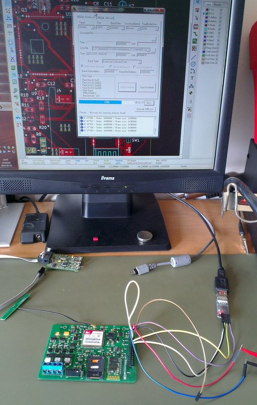
Before wiring things up though, pay attention to voltages. SIM900 ditital I/O (UART included) works with 2.8V levels (absolut maximum is 3.1V, see electrical characteristics chapter in datasheet). In my system on picture I am using voltage shifter ICs even though I have 3.3V microcontroller and it is tested that SIM900 tolerates 3.3V logic. Your cable is rated as TTL so it will most probably generate 5V signal on TX line – direct wiring is asking for trouble. To cope with it you just one shifter (for USB->SIM900 direction); I have PL2303HX based converter and it is capable to read 3.3V logic so SIM900->USB direction can be left intact.
With voltage shifter(s) in between what you just need to do is to connect typical two USART devices: SIM900 RX line to your RS232 TX line, and TX of SIM900 to RX of RS232. Next to it you need to power up breakout board according to documentation.
Before flashing you can check if connection is ok — stick your USB-RS232 bridge to computer and use any terminal (putty, Bray terminal etc) with correct baud rate and try to send regular command (like simple “AT”) and see if you get response (“OK” back).
If your physical link is ready then flashing is what I have already described. The idea is that you need to run flashing software BEFORE shorting NRESET pin because bootloader of SIM900 waits shortly on startup for special instructions from flashing software to ignite reflashing process.
Good luck.
Hello Andy!
I’m working on the SIM900A GSM/GPRS module.. And today (after 2 days) I realized this problem too.. I bought this little board fromChina… fortunately it tolerates TTL, so I use the same FTDI cable like Carlos. And after all my Queston is: How can I know that which Firmware update do I need?
You do not have much choice. It is a hack, trial and error process. The only factor I was using was matching flash size (32/64MB) and using plain SIM900 firmware (with M letter). You can play though with any firmware version you want. As long as bootloader is not screwed up you can reflash anytime. If you are curios on detailed differences between standard and enhanced firmware etc, then take a look on docs linked next to collection of firmware I mentioned in my post, or talk to Dost Muhammad maintaining this collection.
I solved the problem with: “1137B08SIM900B32_ST”
Hello, nice project.
I am experiencing the same issue with SIM900A. I just wanted to ask, what do you think about this problem. GSM modem answers always +CME ERROR 10 when I type AT+CPIN? This error usually shows up when SIM card detection has failed, but do you think it is because of net lock this time? Should changing the firmware help about it?
Cheers!
Is it your circuitry or some Chinese breakout board? If it is your own wiring, double check you have all connections, caps etc in place, since “SIM not inserted” can be both hardware and software issue. I have read about this error caused by firmware but this was SIM300D (ancient times). So you have to experiment. Flash different firmware to module and if it does not help you can always rollback flashing SIM900A firmware again.
Hi, thanks for answer. It is some chinese breakout board: http://goo.gl/P4QGEr.
I realized that my SIM900A is 32-bit version and there is no 32-bit firmware for SIM900, so I guess there is no help in my case. I tried to flash 64-bit firmware like you did, but the system blocks.
The 32 and 64 is size of embedded flash, so 64MB firmware for SIM900 will not fit into 32MB chip of SIM900A. Bad luck if yours is really 32MB :/ Did flashing tool reported any problems flashing too large image? I got once non-responsive system when flashed wrong firmware, maybe you should have try different images once you mastered flashing iteslf?
Interestingly, it did no report any errors, flashing went just fine. I tried many SIM900 firmwares, without success 🙁 Ok, finally I know that the problem lies in the flash size.
Have you also tried 1137B09SIM900B32_ST like mentioned here?
Hi, i also bought this little module without reading first that it won’t work in Europe. :/
While reading your instructions, i found this particular problem in order to comprehend them. You mention about an NRESET pin…
My issue that the breakout board that i have, only has the following pins:
VCC, GROUND, RX, TX and a “KEY” which i use in order to turn it on by following a power up sequence. A picture of it is here: http://i.imgur.com/jSs7dsH.jpg
So my question is, do you have any idea of how i can follow your tutorial with these pins exposed to me? Is KEY the NRESET pin you refer to?
Thanks in advance, you’ve done a great job explaining this!
P.S. Wish there was a tool i could do all these in Linux, but i guess i will have to get a windows machine to try the flash tool. :/
No, KEY is PWRKEY (pin 1) and the NRESET is pin 16, see datasheet page 13. So you need to solder extra wire to pin 16 to deal with flashing. The other lines you need (Vcc, GND, RX and TX) you already have exposed. Good luck!
I was afraid of that. :/ It might get messy, but i guess it is no use to me as it is at the moment, so i have nothing to lose…
Thanks for your help! I’ll let you know when i try it. 🙂
Pin 16 is NRESET and the adjacent pin 17 in GND, so just briefly short them with a flat screwdriver, directly on the SIM900.
SIM900A GSM/GPRS Module, Frequencies: 900/1800MHz
I have a few questions to unlock this module’s frequency bands for use in the USA. First off, I understand this module needs to be flashed with SIM900 firmware. The instructions I’ve found on flashing are very confusing. I understand there needs to be a TTL Level (USB /Serial) communication between the computer and module. I’m using a Bluetooth USB dongle in the laptop and a Sparkfun Bluetooth Silver Mate connected to the module for flashing.
First I need to know which port (com#) to connect to using my Sparkfun Bluetooth Silver Mate Antenna. I know this is specific to each computer and protocols available, but what is the easiest way to get the dongle and Bluetooth Silver Mate paired up?
Can I use AT commands between (Arduino’s serial monitor, BT dongle in PC) and (Bluetooth Antenna, GSM module) only?
Once I figure out which COM my Bluetooth Silver Mate and GSM module is on, then I can use the SIM900 Series Download Tool Develop 1.9.exe software to update my SIM900 firmware. HOWEVER, I’m stuck on step 1 and 3.
Step 1: Power up your SIM900A module to respond to AT commands in auto-baud mode (AT+IPR=0). It means you must wire powerlines, do power-on sequence with PWRKEY etc.
PWRKEY is a pin on the SIM900A. What exactly am I suppose to do here? This is where I’m stuck. Do I need a sketch running to use AT commands? What does it exactly mean to wire powerlines and do a power-on sequence with PWRKEY etc??
Step 3: Short NRESET (pin 16) to GND for a moment. Right after it reboots flashing tool will start pushing data.
Do I really need to temporarily solder on wire to the NRESET pin of the SIM900A for shorting to GND?
Once I ground NRESET pin do I leave it grounded until the new firmware is installed or is this just a quick GND pin and release?
From what I understand if I had an Arduino board with the FT232 chip or a FT232 USB breakout board, then I wouldn’t need to directly access pins on the SIM900A. Is that true? There is mention of an “Arduino approach”.
My SIM900A GSM module:
http://www.ebay.com/itm/201209981501?_trksid=p2059210.m2749.l2649&ssPageName=STRK%3AMEBIDX%3AIT
Evan,
I know instructions may be confusing as they assume user played with SIM900 and is able to wire things up. Let me give you some tips though:
ad step 1) PWRKEY – go to datasheet chapter 4.2.1 and learn power-on/off sequence. You use it here same as for powering up SIM900 for regular use, the same idea, to startup SIM900 UART for your commands. You can do this from firmware (arduino sketch) if MCU can drive PWRKEY.
ad step 3) NRESET – you can temporarily solder a wire you will use to touch GND; in my board I have used just tweezers because I have this pin close to GND pad, it is up to you. You need pulldown NRESET to GND only for split second: if you succeed you will see immediatelly firmware tool (on PC) pushing data to SIM900.
ad FT232) you can go arduino of course, I never played with Arduino as I go bare-metal design so I cannot help you out here. FT232 is just USB-to-UART bridge, so either you use this one or dongle with FT232 onboard.
Hope this helps 😉
I appreciate your responses. What software do you use to send AT commands and receive modem messages?
You can use any serial terminal app like PuTTY on windows or screen on linux/osx. As EE/CAD is best supported on Windows on this system I prefer Bray Terminal.
The serial data I’m receiving is cryptic and unreadable.
Garbage on serial is in 99% caused by mismatched baud rate — device is sending data with different speed than your terminal interprets it.
I’ve taken your advice and installed Bray Terminal. I’m connecting to the correct COM port and now able to set my baudrate to 460800. However, when I send the command AT+IPR=0 no RX data is returned. I tried adding the +CR option, AT+CPIN, diff baudrate 115200, but none of these things helped me get RX data returned from the SIM900A modem. Any ideas? Thanks.
From “AT command manual” you can get that SIM900 will send sequence of chars right after startup (see chapter 1.4), make a test and keep terminal connected when you reset/powerup SIM900, you should receive some chars, whether synchronization bytes or RDY message. If you do not see anything on start you may suspect at least RX line problem if not hardware/firmware one. If you get these chars on start, then check if you have echo enabled (ATE1 command) to get OK feedback after AT+IPR command. Also if you already started flashing and did not finished your module is stone dead and will not respond untill you reflash successfully right firmware. Ultimately troubleshoot your hardware with scope :/
http://m.ebay.com/itm/251757743209?nav=SEARCH
how about wiring this module with ttl
how about the nreset?
About TTL ask the seller: no schema attached, board is blurry and I am not a wizard :).
You need NRESET to be triggered just once so it can be done ad-hoc on any board using any conductor. On this board it is even easier since pin 16 looks like wired to dedicated “RST RESTART” pad.
Thanks for your help. I upgraded the firmware and it works perfectly here in Spain.
Juanma,
I’m using the same GSM module as you are. Did you need any other hardware to read the RX data coming from the modem? Maybe a FT232 chip? Could you please explain your process to get this working? Thanks!
Evan, I read again your first post where you mentioned some BT based USB-USART bridge. Maybe this is your problem, how do you power-up the one on GSM module site? Is this part working fine? Why not spent $2 for simple cable USB-to-USART? I use couple of these all the time for my breakouts, works like a charm.
This must be my problem. I was hoping the USB BT dongle paired (in PC) with the Sparkfun BT Antenna (connected to GSM module) would provide the USB -To-UART bridge. I power the GSM module with 5v provided to my breadboard thru the Arduino Uno.
I have a sim900a module, when I power ON it , Sim900A only sends me III and no other anything such as RDY and so on,
Could you please help me to solve this problem?
99% you have autobauding and SIM900 just waits for your command 🙂 Read introductory chapters of “SIM900 AT Commands Manual” to understand that SIM900:
a) sends always some chars at the beginning (00 49 49 49 49 FF FF FF FF) with fixed speed of 115200 b/s, you see only 3 chars like “III” because your modem speed is too slow (about 3 times slower), you can ignore these chars,
b) in auto-baud mode SIM900 it is not sending “RDY”, it is waiting for you to send first command and based on your speed it will use the same modem speed as yours. What you need to do is to send “AT” command (upper case without apostrophes) and then SIM900 should respond with “OK” and some extra CRLFs around,
c) if your SIM900 module is set to fixed baud-rate (programmed with AT+IPR command) you need to know it; in this case you need to walk over each possible speed and power on each time and send “AT” command to see if SIM900 can get it… it is rare situation, SIM900 goes from factory with auto-baud setting so look at (b).
Manual is your friend (RTFM they say) and there is no way to cut through learning curve. It is even more troublesome if you have many moving parts (many variables in your equation like: first time using SIM900, first time using USB-USART bridge, you own custom SIM900 design w/o breakout board, … and so on). Keep going though, enormous satisfaction will pay your effort back 🙂
i have SIM900A with me in my project. i am facing RTC issue. my device RTC get lag if i set it correctly after 8 hrs of continuous run.
Are you talking about RTC inside SIM900A accessible via AT+CCLK command? I do not use built-in RTC, I have external one because I rarely use data transfer powering off the whole GSM block. External clock is also easy to calibrate if needed. What is deviation in your case (after 8hrs of run)?
You can add routine to your firmware and get GSM time to update your clock as frequently as you need. This is how I manage my external clock: I use AT+CLTS and my operator on network logon after AT+CPIN sends USSD asynchronous timestamp as *PSUTTZ response which I parse and propagate to external RTC.
Hi
I have a sim900A mounted on a breakout board with the moniker mini v.3.8.2. it appears to accept TTL voltage levels at 3v and 5v. (pins for each).
I have flashed a number of different firmware versions from Dost’s website. All appear to complete successfully. However when they are finished, I reboot the board (power cycle) and it remains in bootloader mode. the two LEDs flashing rapidly and continuously.
I’m uncertain as to what this signifies. either (i) the flash loader software is wrongly reporting success (it does occasionally report errors too); or (ii) the chip is fried and reporting arbitrarily; or (iii) there is some magic to getting out of bootloader mode that is more than simple rebooting.
I’m using an FT232RL on a ‘Duino Nano, with the 328p bypassed. TXTX, RXRX etc. I’ve tried using a custom 8u, a prolific, and a CH840G and none work (freeze at the flash downloaded point).
If there is any advice on getting out of bootloader mode that would be great.
thanks
Justin
Successful flashing means just memory was written correctly, incompatible firmware won’t work though, and as you see in most cases it simply doesn’t. I am not Simcom engineer so I cannot interpret misbehavior for you. If nothing else works you can flash SIM900A firmware back. You may also ask seller for support with firmware replacement :/
Hi Andy
the wrinkle is that the same behaviour occurs with the original firmware too. hence my thought that this was/is an issue with either the chip being fried or perhaps my ignorance in how to get out of bootloader mode.
any thoughts?
thanks
Justin
Then you have problem hard to isolate – with single SIM900A module you cannot tell whether it is this particular module problem or anything else. I had bunch of working modules on my desk when I started: meaning less variables in equation :] I also cannot find any docs saying STATUS/NETLIGHT fast blinking together is bootloader failing to start application. Contacting your supplier or producer (simcom) seems to be the only option.
Hi Andy,
I wonder if you or any of the readers can help me with this: I just updated my SIM900 board and everything worked fine (I got the “Download done” message at the end), except that, after power Off and then On again, there is no way to get any response from the module to any AT command. It looks like frozen… I have tried (at almost every possible standard speed) AT, ATr, but I have had nothing back. The netlight LED, completely Off… I am honestly out of ideas at this point. I any of you guys have had a similar problem or come up with any ideas, it is appreciated very much in advance.
norb, I have seen dead module when flashed wrong firmware. You can always reflash again, use other images or restore original firmware you had flashed by factory (as long as you have made a note of firmware version in first place and there is such firmware file for download). Make sure you have right firmware, you said you have SIM900 and this post is about SIM900A.
Success I followed exactly your instructions and everyrhing works!!!
Now I have a SIM900A registered to Wind GR
Alex Greece
Amigo yo tengo el mismo problema con un modulo sim900a favor me podrias indicar como resolvio su problema con el registro. gracias
English please, Orly. If you still have problems with registartion after flashing then try SIM from different provider or check radio bands supported by operator of your SIM card(s).
Hello alex, can you please let me know if i can use Vodafone sim card to sim900a?
Hi,
I recently got a SIM900A module and found this page with instructions on how to flash it, to be able to use it in Europe.
I’m using a USB-RS232 cable and a MAX232 to convert 232 levels to TTL. Using a MOSFET levelshifter I shift 5V TTL to 2.8V TTL the module needs.
Using 460800 baud I only ever got “Error during change baud rate”, So I changed it to 115200 baud, which repeatedly gave me “Error during flash erase”.
After a few tries it seemed to work as it showed “Flash erased”, “Downloading application in Flash.”, but shortly after it failed:
“Error during acknowledgement waiting” “Error during download application in Flash” “Check target settings”
So, now flash is erased and no new firmware was flashed to replace it… I have not been able to power up the module again, that is, after doing power cycle, netlight LED will not blink or light up. Sending AT commands simply return the commands I sent back to me, but no “OK” or anything else.
When I try flashing firmware I get “Error during acknowledgement waiting” “Error during download data via Boot ROM” “Error during download loader in RAM” “Check target settings”. Which is exactly what I would get if I disconnected the module and started up the flashing tool.
Is there any way that I can get new (or the old?) firmware on my module again, now that flash is erased and the process failed afterwards? Or is there no way now that the flash is gone, to get new firmware on it? I used MAX232 to do the flashing, but most of the posts I have read people are using FT232, should I buy a FT232 chip to be able to flash correctly or is there no need to bother and is the module already lost?
I have not experienced such misbehavior myself. Some people could solve it using different adapter for UART. I use all the time a dongle based on CP2102, see my other comment, quite useful stuff so I have couple of them. It is darn cheap so you can give it a try.
Thanks for your instructions. I have SIM900A MINI V3.0.2 with 1137B03SIM900A64_ST_ENHANCE firmware and I flashed the same firmware as you did and it worked. Now I can make calls but strangely only to non ANDROID phones, but its still better than nothing. Few things may confuse people: When flashing there shouldn’t be any jumpers on TTL pins because you will get an error, and you need to short NRESET and GND only for a second, you don’t need to hold it for the whole flashing process. By the way I flashed on virtual WinXP (VirtualBox) using USB- SERIAL adapter.
EDIT1: It appears I did not put ; after the command so ATD8xxxxxxxx returned NO CARRIER and the ATD8xxxxxxxx; returned OK and phone started ringing.
Tomas, glad to hear you fixed your board. Regarding NRESET I guess my wording is not precise enought as I said “Short NRESET (pin 16) to GND for a moment” simply to initiate reboot process.
Andy- Thanks for all of the valuable information here.
I have a few of the SIM900A modules and flashed them with SIM900 firmware without problem, and verified the version once restarting them via PuTTY.
I am in the US, and I do not seem to get any GSM signal using a T-Mobile SIM once the modules are upgraded to the SIM900 firmware..
I have SIM900 modules as well, and I know the SIM card I have works with those.
Do you have any pointers for troubleshooting? Unfortunately right now, I am not in front of the module, but I’ll verify everything tonight and check back. I just wonder if anyone have gotten the SIM901 to work in the US and which carrier they were using.
Thanks,
Jeff
Jeff, I am not sure radio bands used in US and as you know SIM900A has two-band while SIM900 quad-band radio. Chances are T-mobile is using band not supported by A-version radio hardware. This is my best guess though, you can always get some other telco SIM card and try it out.
Thanks, nice project
help!
After sim900A firmware replacement (1137B01SIM900M64_ST_ENHANCE Europe) and restarting at once and flashes the POWER Netlight led, did not go to any AT, is not only possible .. CALL Redy sebugRX..TX portokon.Próbáltam B03 replacement firmware firmware is the same !!
Help me!
segítsetek!
sim900A firmware csere (1137B01SIM900M64_ST_ENHANCE Európa) és ujraindítás után egyszerre villog a POWER és a Netlight led, semmilyen AT nem megy , nincs CALL REDY.. kizárólag a firmware csere lehetséges a sebugRX..TX portokon.Próbáltam B03 firmwaret is ugyanez !!
Segítsetek!
I’ve done many times flashing SIM900, but on the last series, I’ve got on eBay, I get an error and can not do flashing!?
“Update option does not support this flash!”
The procedure is known to me, and I have not changed, neither hardware nor software.
I have a feeling that something has changed in the last series, so that the SIM900A to SIM900 flasing no longer possible! ???
Does anyone else have the same experience in the last month or two?
Ognjan.
You can google “Update option…” message in post from 2011 so I do not think you are experiencing a new kind of issue here. Maybe you bought SIM900A with 32Mbit flash instead of 64Mbit; observe that SIM900 firmware comes only with 64M size and it will not fit in this case (see earlier comments here). It is just a best guess since I cannot check this out myself.
Yes, you’re absolutely right! Is there a solution to this case? Where to find firmware for Europe of 32M?
Bad news: I do not think you can fix it. BTW I have not found any information how to detect whether SIM900A is 32 or 64 mbit; I guess simcom cut the costs replacing flash without notice.
The only advice is to get full-blown SIM900, it is not that expensive. On aliexpress you get single SIM900A from $7 and SIM900 from $9 (of course you need also hotair to rework it if you bought breakout board with SIM900A module). SIM800 can be alternative depending on required functionality.
I was able to remove PH-NET PIN restriction on SIM900A 32 bits version.
I successfully uploaded “1137B09SIM900B32_ST firmware” with “SIM900 Series download Tools Develop 1.9” download tool.
However after a couple of tests i found this firmware is not able to send emails.
I think the trick is to try to reflash SIM900A_32 with SIM900B_32 firwmares.
Thank you very much for this instructions. I used the 1137B01SIM900M64_ST_ENHANCE.cla firmware for an ATK Sim900A, which I bought in Central Asia. Now it works perfectly in Austria. Klaudia.
Please where I can download 1137B01SIM900M64_ST_ENHANCE.cla?
Hello andy, i am using a SIM900A (S2-1040V-Z1K0H)
I am not able to make the flashing data start uploading the firmware. I am using a vodafone sim card (Greece).
Any ideas?
Hi George, SIM card has nothing to do with flashing itself, it either works with specific firmware or not. Double check all elements; make sure that PC communicates with SIM using cable UART etc. I cannot say anything more, most people get it done, I guess you do some minor mistake that prevents you from reflashing, this is not that hard, just re-read different receipts, sleep over with it etc. If it still does not work, PM me and I will send you Alex email, maybe he can help you sort it out in your native language 😉
i need to know about the version of SIM900A s2-1040v-z0958 and SIM900A s2-1040v-z1k0h
bothe are equal or not, can i replace z0958 instead of z1koh
This guide worked for me…
http://www.symbola.co.uk/safe/SYM-DOC-COM-1-V1.php
Hello!
I’m keep getting this error when trying to flash the SIM900A.
Any good ideas?
I tried several files I found, including the one I created (as backup) using the Upload menu of the tool.
1’33″438 – Index: 0x7C0000 / Frame size: 0x7E0000
01’34″110 – Index: 0x7D0000 / Frame size: 0x7E0000
01’34″813 – Index: 0x7E0000 / Frame size: 0x7E0000
01’34″813 – Index: 0x7F0000 / Frame size: 0x7E0000
01’34″813 – Erase flash complete!
01’34″813 – Start to write flash!
01’35″016 – Index: 0x800 / Frame size: 0x800000
01’35″203 – Index: 0x1000 / Frame size: 0x800000
01’35″407 – Index: 0x1800 / Frame size: 0x800000
01’35″594 – Index: 0x2000 / Frame size: 0x800000
01’35″797 – Index: 0x2800 / Frame size: 0x800000
01’35″985 – Index: 0x3000 / Frame size: 0x800000
01’36″188 – Index: 0x3800 / Frame size: 0x800000
01’36″344 – ERROR Error:Start writing flash command error! (264)
thank you in advance!!
Nikitas
Hello there, recently I have flashed my sim900a, but I have noticed that light that shows power on, is less bright. I cant connect to the AT commander anymore. Is there Any way to flash it back or flash it to work normal? IT took me long time to get it flashed and now it doesnt work… Help!
I didnt get firmware,my module current version is 1137B09SIM900A32_ST_ASIA
I did the same process using 1137B12SIM900M64_ST firmware but, after doing the process my module is showing noise on the command window. I cannot give it any command not even AT. Its just giving a noise kind of thing on the window and keeps on doing this till i keep it powered on. I am using PuTTy for this.
Hello ANDRY
I have an issue with SIM900A concerning this command (AT+CIPGSMLOC=1,1,3 )
it returns the value “not allowed”. What should I do to resolve this problem? Thanks in advance.
Best Regards,
Hey,
What should I do it if flash uploader shows the message Power Up the target? I tried connecting RESET pin to GND for a while – nothing happened.
Hi Andy,
I flashed my SIM900A module a month ago. But it suddenly, stopped working and return to the initial state, what cause may be responsible for this?
Thanks in advance.
Although i work this project, it does not work at all. Please help me.
To fix and unlock the network in Europe,( Portugal only 32Mb) our website will help you
https://norlinux.000webhostapp.com/2018/10/unlock_network_sim900a_europe
Pingback: Como atualizar o firmware GSM SIM900A – Mundo dos Microcontroladores
Pingback: Desbloquear a rede ou bloqueio de país GSM SIM900A – Mundo dos Microcontroladores
I followed the instructions (got FW here: https://github.com/dimircea/Arduino/blob/master/examples/Sim900/firmware/bin/1137B01SIM900M64_ST_ENHANCE.cla)
and u halped to fix my SIM900A.
Thanks a lot!