
Thunderbolt that hits near a long cable line can induce spike of hundred of volts. Budgetary RS-485 driver will not protect circuitry from damages caused by over-voltage and over-current. While scorched prototyped device makes constructor sad, failure to bunch of production-grade devices leads to financial impact: loss of hardware, maintenance time and penalties from SLA breaches.
My first considerations focused on choice of right cable – I picked up three twisted pairs in common aluminum shield, sealed in waterproof petrogel, wrapped by poliethylene tube. This cable can be burried in ground easying routing and protecting cable from accidental cuts or vandalism. Shielding should make is resilient to EMI induced by thunderstorms. As the only 4 lines are used (ground, power, signals A and B) extra pair can be used as spare cable reducing need to cable replacement when one or two lines of already mounted cable are damaged.
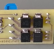
Array of 1500 watt TVS
Since modular approach makes possible to use any cable, in future for some reasons different cable can be used exposing electronic components to surge threats. To make I/O safer I have chosen set of power bidirectional TVS (transil) diodes to protect transmitter from overvoltage. Grid of 1500watt transils is assembled on input to RS-485 line of first version of transmitter and test tools (USB-RS485 adapter).
These precaution measures did not relax my vigilance. I got back to review protection circuitry, especially considering main logger unit way too expensive in terms of effort just to be fried in prototype phase. As protection was was never in scope of my interests I spent hours looking for different approaches. I was aware of spark gap devices yet I was new to miniature GDTs – gas discharging tubes or gas tube arresters: small two-node devices, size of coffee bean, that can ignite electric arc inside when specific voltage is breached. While TVS is very quick in dumping overvoltage (it switches to full current in within few nanosecond) it has to dissipate all excess energy as heat: in worst case simply burning and opening circuit again to surge killing protected circuitry.
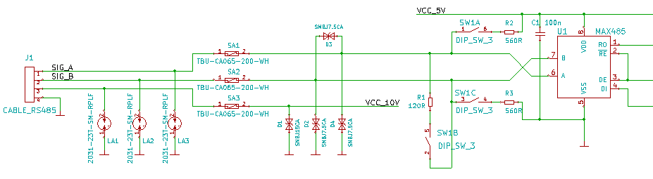
Three stage surge protection
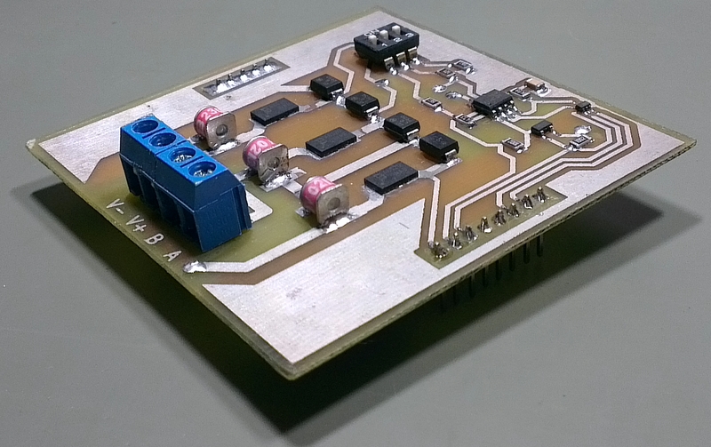
Later I found complete approach which I have adopted to my case with 4 instead of 3 lines. In this model excess energy is first taken by spark gaps, then behind GDTs current is being limited by dedicated components to finally cut down voltage spike to level below absolute maximum ratings of protected circuitry. In this case smaller TVS diodes (600 watt) are enough. While spark gap and TVS diodes are well understood I could not find technology behind mysterious current limiter, called by Bourns TCS (Transient Current Supressor) or HSP (High-Speed Protector); only one whitepaper mentions using field effect (the MOS structure) in TCS. Anyway I have applied this proven three-stage approach in main unit of data logger being constructed as shown on right side.
See also other related articles:
[posts_by_tag tag=”WLS”]


