
Once the signal from sensor is converted in ADC it has to be processed and delivered to remote master unit. Having extra local measurements sources, like temperature, it has to be combined altogether. Multiple transmitters coexisting on single line (bus) to master unit complicate protocol of data exchange. A microcontroller (MCU) is most flexible way to make it all happen.
MCU responsibilities
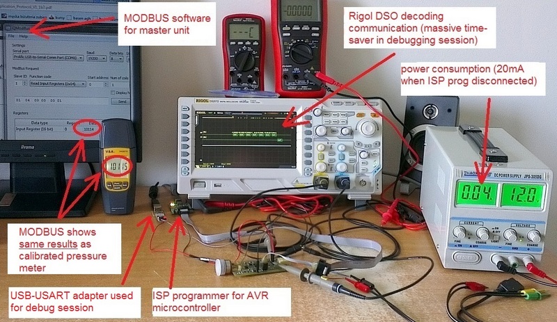
Microcontroller handles communication with its sensors. The transmitter measure two physical parameters – pressure, that turns into water level which is available through SPI protocol of ADC, and temperature measured by DS18B20 chip accessible via TWI (I2C). Remote communication is done via RS-485 and it is hardware USART built into MCU that drives it. MCU also implements MODBUS RTU protocol over RS-485 as this is proven and widely adopted protocol making transmitter universal and vendor-independent device.
Raw data from local sensors is converted before exposing to remote master unit. Each transducer is slightly different so voltage-to-pressure function must be calibrated for each single transmitter. MCU stores such data in EEPROM and calibration is done with the only access point to transmitter – MODBUS over RS-485.
Aliasing effect
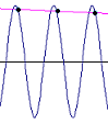
As in outdoor conditions water surface usually fluctuates, forming significant waves when disturbed by wind or floating objects. It impacts level measurements: if transmitter latches only single measurement it is highly unreliable. To counter-fight waves MCU collects multiple measurements in cyclic buffer and calculates moving average over it.
Averaging is exposed to another issue. Water surface pulsation can be close to frequency of measurements or its harmonics – this would lead to phenomena called aliasing and calculate completely wrong result. In turn the transmitter uses configurable irregular pace of measurements to diversify sampled values.
Fitting features into MCU
Natural choice was to use Atmega8, an 8-bit microcontroller with 8kB flash memory and all necessary hardware peripherals to drive the subsystem. To assure quicker debugging in quite complex implementation, I decided to use newer variant – Atmega88 – enhanced with JTAG debugging capability.
For MODBUS I took FreeMODBUS library as its license opens up commercial usage free of charge as well as it saves my time on own implementation. Free license has its unexpressed limitations that I discovered after API review: support for multiple slaves on the same bus is unavailable and it does not have API for master-unit functions (for that commercial paid license is required). It is enough though for first single-slaved WLM. To make it compiled I created Atmega88 porting, which is not supported out of the box. The minimal set of functions for binary mode (MODBUS RTU) has compiled into 4kB of flash and 300 bytes of RAM, half of resources of MCU.
The code for SPI protocol for ADC I developed myself, avoiding dozen of problems thanks to my new lab toy – Rigol DS2072 oscilloscope equipped with multiple discreet protocols decoder (but that is separate story). This piece of software took nearly 5kB of flash, which combined with TWI (I2C) communication with DS18B20 temperature sensor, already exceeded limit of available memory. And I was still missing some of core functions.
Fortunately Atmega168 with its 16kB of flash is pin-compatible and has nearly completely compatible internals with Atmega8/88. Re-soldering MCU and slight changes to code made it working within an hour. Final firmware takes 12kB flash and 800 bytes of RAM leaving some room for enhancements.
Microcontrolled WLM trasmitter
FreeRTOS consideration in context of transmitter’s features became unreasonable for two reasons. Firstly, different tasks undertaken by MCU are relatively short and can be sequenced without overlap; single loop with conditional commands turned to be good enough scheduler, making system responsible even for couple MODBUS requests per second which is far beyond needs. Secondly, FreeRTOS on Atmega168 requires 6kB+ of flash (as I have already blogged here) exceeding flash limit again.
See also other related articles:
[posts_by_tag tag=”WLS”]


