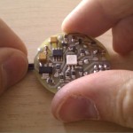
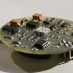
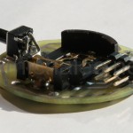
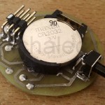
While I was finalizing e-snowflake project, I imagined that single RGB 5050 LED would create nice rainbow effect if placed inside a ball like ping-pong. You can find plenty of such projects on the net, this one was heading to embed everything within ping-pong, battery included. The design challenge was to create PCB small enough to fit into ping-pong, design electronic on/off power switch and to supply LED with forward voltage drop higher than battery voltage.
The concept
The core part producing rainbow effect is MCU driving single RGB LED. Most of the hardware complexity manifests in two other concepts: step-up voltage regulator with stabilizer and electronic on/off power switch. Let me discuss all three major design parts.
Single attiny13 MCU drives 5050 RGB diode and using phase modulation of driver lines any rainbow color and brightness can be produced. The T3 transistor was introduced to isolate cathode LED lines when connected to ISP programmer. In theory when programming PORTB pins should be in default state, i.e. high-impedance, keeping T3 in high-impedance too. In practice when ISP programmer is working LED is blinking with dim light anyway – it means that in next schematic version R7 and T3 would be simply dropped.
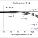
Voltage regulator part is responsible for keeping voltage higher than battery can supply and stabilizing it when battery voltage drops over time. Higher voltage is necessary to keep LED operating because green and blue components have 3.1-3.3V of voltage drop in working conditions. The lithium-ion CR3032 button-battery that was chosen gives 3.1V when fresh and decrease output voltage down to 2.2V at 95% of its lifetime (see attached charts) and cannot power-on RGB LED.
The solution is based on LM2660 charge-pump in voltage doubling configuration giving output voltage from 6V down to nearly 4V. Changing voltage over time would lead to LED brightness dimming over time as well as 6V power supply would also exceed maximum rating for MCU. The LM1117 low-power step-down regulator is adjusted with R5-R6 divider to create 4.0V on output placed below doubled voltage of discharged battery. LM1117 introduces voltage dropout when input voltage is close to stabilized voltage – from datasheet it ranges from 1.1-1.3V for 100-800mA of load current respectively. I observed however that for fully operating device with 20mA current load dropout was even lower, measured as 1V. For my design it means that when input voltage drops below 5.0V (2.5V on battery), it is no longer stabilized and LM1117 output also drops down below 4V. Good news however is that 2.5V on battery is at the 90% of its lifetime; what’s more visible brightness drop happens when battery voltage is even lower, around 2.4V which is when the battery is almost dead.
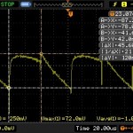
To save on large components to fit on 40mm diameter PBC I skipped filtering capacitor between IC2 and IC3. Despite voltage ripple at the level of 120mV (at 4.0V and load of 20mA) and 10kHz frequency (charge-pump oscillator) the MCU works stable. Since analog part is not used, like ADC, weak filtering is not an issue here.
The last area of circuitry is “electronic power switch”. The idea behind is that one tact-switch can bootstrap power-line as well as initiate power-down phase later on. When device is powered off, pressing tact switch drives T2 and powers on the whole circuitry. While it is still pressed MCU has to drive T1 to keep T2 conducting after tact-switch is released. When the system in powered on, another depression of tact-switch can drive another pin of MCU which can react and cut off T1 and T2 effectively, leading to power down of the whole circuitry. Credits for this subsystem go to the Melanie from PIC forum where you can find detailed description.
Board design
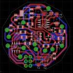
This part was similarly complex to e-snowflake. Auto-router has problems fitting thick wires onto the tinny board. I had to route couple wires move nearly 1/3 of other wires and vias which took me nearly two hours (I am not a “speedy gonzales” of Eagle, that is the other part of the story). Having design ready I repainted on PNG file pads for tact-switch to solder it in horizontal position and let button stick outside of PCB boundaries – this way button can be easily exposed through the hole in ping-pong ball.
Hardware startup
Facing version 1.0 of hardware design I could expect mistakes and omissions. Fixing hardware is more time/money consuming and to save time I decided to run the device in stages. After soldering in voltage doubler and its supportive components I checked this section supplying IC1 directly from external power supply.
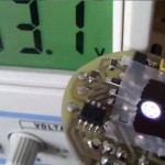
Then I assembled stabilizer part and the problem appeared. I noticed that measured output voltage is not stabilized at all. I suspected damaged IC2 and replaced with the other one getting same results. Puzzled with results, fifteen minutes later I realized my bad – I was measuring unloaded circuitry leading to situation when voltage divider current is far bigger than (nearly zero) output current, completely destabilizing output voltage (doh, I know, I should get back and pay more attention to electronics classes). After loading system with 1k resistor the system was working as expected.
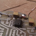
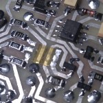
Later on I mounted IC3 and LED with other supporting elements. At that stage I found problems with soldering pads location, they were placed to widely and to mount LED I had to create tin bridges (attached PCB design file has it corrected). To isolate copper tracks under the LED I used a patch made of kapton sticking tape. After that, still using external power supply, I loaded test program to simply blink the LEDs one by one.
In the initial research I observed that 5mA of forward diode current was enough to light it quite bright. Due to different voltage drops (measured as 1.9, 2.9 and 3.0 volts for red, green and blue colors respectively) I used 430R, 22R and 200R resistors. In first run when I was switching different colors one by one I realized that blue led is much dimmer then other and red one was still little brighter than green. To get similar level of brightness I redesigned resistors to use 5, 7 and 10mA for RGB colors respectively finally using 300R, 150R and 100R.
The final part of device to assembly was “electronic power switch”. I kept it to the very late moment because it requires interaction with microcontroller. All I needed was to add few lines of code to drive PB4 pin some time after bootstrapping MCU and reload firmware. I was delighted that powering on worked from first run.
I did not avoid serious oversight however – second pin used as input from tact-switch (for power down function) is RESET pin of MCU. While device is working button depression leads to MCU reset. I had two choices: either defuse manual power-off function (MCU still can power itself off using second PB4 line) desoldering D1 diode or I could program PB5 as regular input and disable reset function by setting RSTDISBL fuse bit. I have chosen first option because disabling reset disables also ability for serial programming (ISP uses RESET line) and to reprogram attiny13 I would need to use high-voltage programming with resoldering MCU. Too much hasle for simple toy.
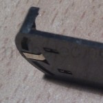
Soldering battery socket was also tricky one: when socket is placed on PCB one of pads is hardly accessible from top side. Using hot air is not an option, plastic basket would melt easily. Finally I soldered it to PCB but I found it difficult and I could not avoid melting a bit the plastic basket, even though I was cautious and using tinny soldering tip.
Firmware
Firmware seemed to be fastest part of desing with codebase taken from e-snowflake. In theory the code worked fine after quick porting. In practice it worked fine with simple color changes. When I started rainbow effect implementation I realized why attiny is “tiny” microcontroller – if you are using heavy computations in plus frequent and also complex interruptions, glitches are guaranteed faster comparing to “mega” MCU with higher computational power. I had to use couple tricks to make this working. Firstly I droped complex effects and simplified rainbow calculations. Secondly I skipped caching for PWM procedure and linearized PWM computation. Finally I speeded up clock disabling divider (CLKDIV8) and went after fastest built-in clock running at 9.6MHz. More power consuming setup but still irrelevant comparing to LED power consumption.
Final results
Final work was purely about tinkering. To place device into ping-pong I sliced it only in 3/4 and pulled through. I could not find any glue it stitch it back so I used transparent sticking tape. In the evening or at night, glowing ping-pong looks really nice. Measured current on for fresh battery is floating around 15..25mA, and with average of 20mA and 220mAh of CR2032 leads to 11 hours of constant light show. The only drawback of glowing ping-pong is that you cannot play it anymore, it does not bounce 🙂

