I remember my first digital circuit made up when I was teenager, an electronic dice, made of TTL logical gates, driving 7 LEDs formed to display any combination of dots of thrown dice. I realized it would be good microcontroller playground. Flexibility comming from programming allowed me to plan a bit more comple hardware: double dice display plus sound buzzer.
Years of being software engineering have influenced my approach to the problem, that is in fact not that far from hardware engineering discipline. To minimize problems I went methodical way: I collected “requirements” first which allowed me to make a design blueprint. After that I did “proof of concept” with breadboard, tuning up hardware setup. Having fixed hardware design I built the device and finally made it alive with firmware written in C language.
The dice with double display and buzzer were cornerstone of assumptions. The next one was standalone type of module, powered by rechargable batteries, size of AA or AAA; more compact battery like CR2032 does not have enough capacity to light multiple LEDs for too long. Also the size should allow easy handling – LED matrix should be big and bright enough to observe by group of people playing a game. Push button to “throw” should be most easily accessible. Over time I realized that to preserve batteries power switch might be necessary, I do not have experience with shutdown/standby mode of microcontroller so I could not decide if it is OK to leave circut wired to batteries for a good. Thanks to Julia, youngest household member and Monopoly game specialist, I was reminded some games require one die, other two dice; therefore I needed mode switch too.
Schema
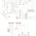
First step was a design of LED matrix made of 14 elements. Attiny2313 is not able to drive that amount of diodes directly at least for two reasons: you would run out of port pins for other purposes (switches, buzzer etc) and, in worst case when all LEDs are on, total current would exceed maximum allowed to drain from microcontroller. Transistor based multiplexer was simpler and faster approach. LEDs formed in 4 columns by 4 rows matrix could be driven by 8 line in total, where anodes are wired to columns and cathodes to rows. Multiplexing is done column by column (only one column at a time is active), it means that in worst case when 4 LEDs of columns are light on, column drains current of about 4x20mA, while each row drains 20mA. This is why rows are connected directly and columns are driven by transistors. Column activation is done same as row activation, by setting zero to on port port output; it toggles PNP transistor into saturation and sets emitter voltage near to Vcc.
(Note: if you want to observe multiplexing, simply set higher timer prescaler in firmware).
Sound emission is based on buzzer desoldered from old PC motherboard. Similarily to LED matrix, driving electromagnetic buzzer requres more current that open-drain output of microcontroller, so PNP transistor was placed in between. Next to base polarization resistors R5-R6, I put limiting resistor R7 in case PD4 line is permanently set to zero by accident, leading to Q5 saturation and short-wiring Vcc to ground. I have tested it with breadboard and for battery power it causes brown-out and microcontroller shutdown. D1 diode cuts of negative spikes induced by AC on SG1.
The device does not rely on rigorous timings, therefore Attiny2313 is left clocked by internal RC oscillator; XTAL1 and XTAL2 pins are left floating. In my case I left defaults, 8MHz clock divided by 8 by default fusebit prescaler.
Tact-switch is used to “roll a dice” and is connected to PB5. I have chosen port B since it is interruptible by pin state change. Similarily mode switch (bistable) is connected to PB4 of port B.
Finally, to prevent misconnected power line (negative Vcc), diode D2 will not pass current when reverse polarity is applied. Metal-semiconductor junction of Schottky diode minimizes voltage drop by 0.2V only.
To easily reprogram hardware, 6-pin connector is placed. I had to come to compromise sharing PB5 ping for tact-switch and for programming MOSI line. I wanted to have event-driven tack-switch for experiments. It costed me disabling tactswitch while programmer remained connected. I would leave tact-switch, normally open, on shared pin instead of bistable dip-switch; the latter would left MOSI grounded by accident leading to annoying programmer blocks.
Prototype
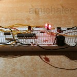
After blueprint phase I had to prove it is valid. Without experience with μCs I had to be extra cautious; years ago I was many times in a situation when I had to re-wire final PCB to make device working. This time I was armoured with breadboard, something you could not find here 15 years ago.
I needed to check LED column-row driver, buzzer and 6-pin programmer; all new for me. 2 LEDs were enought to check the brightness, and port manipulation in program. Checking buzzer possibilities I selected components’ values, especialli limiting resistor (compromise between loudness and max current at short-circuit). At that phase I decided to skip external oscillator and its capacitors.
PCB design and assembly
Designing PCB with free Eagle software was another challange. I did only couple exercises but this time it was from-scratch design. And I wanted to have compact, multi layer hardware.
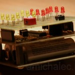
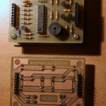
Initially I decided to have 2 layers – top one with LED matrix and switches, and bottom layer with everything else. I end up with additional layer with batteries. Top and middle layers are connected with two 8-pin connectors left aside. I thought they should fit tight enough to leave drill holes without screws, spacers etc. I had to use them for heavy battery layer.
To summarize the only challange was to manually redesign couple wires, where auto-router was unable to proceed (or more precisely, because I was not so good at routing and tracking settings, to allow autoruter finish the job conforming to rulechecks).
PCBs were prepared using thermo-tranfer technique I am strongly advocating – nagative image is transfered to chalky thin paper, then ironed to PCB laminate, and then put to water to soak off the paper. The IKEA’s catalog paper is best I found, its absorbs water immediatelly and soaks off in a minute. After cleaning surface from paper remains, it is ready to picle e.g. in safe sodium persulfate solved in hot water. Within 10-15 minutes PCB is etched. Acetone thinner easily removes printer toner and dissolves colophony. The latter I use to cover PCB with thin layer preventing from copper oxidation and for easier soldering (BTW acetone dries much faster than alcohol, colophony is non-sticky within minutes instead of hours).
Assembly was straigthforward. The only thing worth to mention is goldpins placement – on PCB bottom side instead of top. This way pins of top layer would fit to socket on middle layer, connecting these two part into full circuitry.
Firmware
Tooling was a first issue to solve – I tried WinAVR programmers notepad and AVRStudio, both free versions. Long time spent in Eclipse platform in Java development made me lazy – what I am missing in both tools is support for navigation thru artifacts, starting from files (which header file and where it really is located) to functions, plus instant help with intellisense (show me available methods, variables etc in current context). I quickly stepped back into CDT environment equipped with AVR plugin. I do neglect AVRStudio power, but for quick first steps is not that good. Later, for simulation and probably hardware debugging I will switch back to it, or any other better-fitting tool.
Project layout is more like hello-world style. I avoided over-engineering which is not necessary at a scale of 200+ lines of code with several variables, macros and functions. Single main.c file suffices.
Code structure is quite simple – it has infinite loop in main procedure, interruption handler for user button interactions, and cyclic timer interruption handler for continuous multiplexing of LED matrix.
Display multiplexing is driven by global variables that hold current bit flags reflecting which of 14 LEDs should be light on and off. The client code (from main procedure) turns the number from 1 to 6 into bit flags and sets bit flags. Periodically, with frequency of hundreds hertz interruption handler do the multiplexing activating next column and setting apropriate rows.
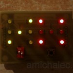
After the hardware was assembled and first multiplexing run, I have seen that red LEDs are brighter than yellow. I could try to modify hardware for different colors e.g. reducing current for red leds replacing resistors, but I quickly realized power of microprogramming – I decided to keep higher multiplexing frequency and introduce kind of phase modulation for columns – I manage to keep yellow columns active 4 times longer than red columns that eliminated this problem!
Registered interruption handler for pins PB4 and PB5 reacts to buttons and sets up global flag, a request for processing. Infinite loop in main procedure checks for processing flag and reacts. The “throw” flag leads to randomization of next dice value, and playing short bleep sound. Then this is repeated couple times to mimic dice rolling on the table and finally stabilizing. Dice value changes are immediatelly reflected by frequent timer interruption running multiplexer. Similarily “change dice number” switch flag leads to short animation.
Summary
I understood 1/4 of attiny2313 possibilities, far away from saying “mastered”. 16-bit timer, PWM, UART, analog comparator or power management are still to be touched.
I have also couple open issues. I could not resolve interference problem: why multiplexing changes sound of buzzer even if PD4 port pin state, driving buzzer, is not changed in multiplexing. I need to investigate delay functions. Why do that give delays much longer than declared, even F_CPU set correctly? Why are they so sensitive to timer prescaler, even though interruption handler has short set of instruction? After all this project stimulates my appetite for more.
If you liked this article, help me to maintain blog on electronics and donate!



After I originally commented I clicked the -Notify me when new comments are added- checkbox and now every time a remark is added I get 4 emails with the same comment. Is there any way you can remove me from that service? Thanks!
That is weird, I tried to PM you using given email address but gmail responded with “permanent failure: DNS Error: Domain name not found”. If you still experience this problem please PM me back.