
Four years ago I made microcontrolled snowflake decor using home made PCB based on toner-transfer process. I got back to this idea late in 2015 to make short batch for family and friends. Second version was about fixing design issues and adding extra features: rechargable battery, USB interface and automatic brightness regulation. Nice looking factory-made PCBs were ready in November 2015.
Enhancements
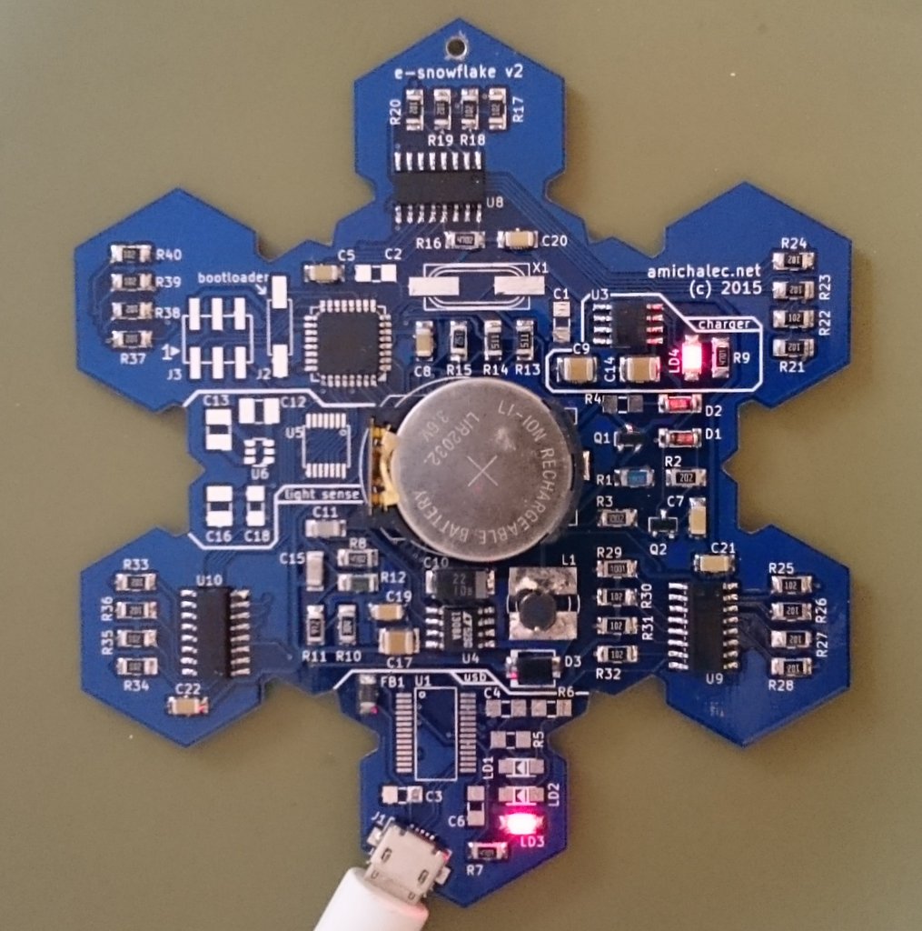
What remained from initial concept was lights layout and MCU: 24 white diodes on six arms of hexagonal board shape plus center RGB diode controlled by Atmega88/168. Driving lights has been modified though, from arithmetic intensive bit-banging to peripheral hardware. 595 shift registers are now driven by SPI interface and each diode of RGB is modulated by PWM counters (OC0A, OC0B and OC2B) minimizing CPU time.
All other subsystems like power switch, thru power-supply blocks, USB-USART bridge, and ambient light sensor, were revision 2.0 fantasy.
USB charging
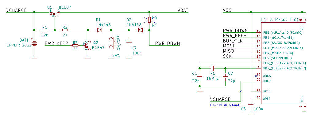
First hand-made version required external 5V power source, V2 was thought to be battery powered. Due to small PCB I started from CR2032 with optional rechargable LIR2032 and MAX1811 as charger. Different working voltage of CR2032 and LIR2032 (1.6-3.1V and 2.8-4.2V respectively) and LED voltage drop above 3V pushed me to add LT1308A step-up DC/DC converter for system power. As in first version system voltage was set to 5V.
Power on/off switch has soft implementation: a design with pushbutton, two transistors, two diodes and couple RC elements, that allows MCU keep power-on or programatically cut the power off. Same way glowing ping-pong is powered on and off.
Micro USB socket allows charging Li+ battery from smartphone charger or connected computer. If FT232RL is assembled onboard also hardware USART of Atmega can be communicated; this way with dedicated bootloader reprogramming could use USB in favor of ISP (like in Arduino environment) or in future custom computer software to redesign visual effects.
Finally, the TSL2561 ambient light sensor placed on front side of PCB gives extra playground for dynamic brightness regulation, dimming lights in darker conditions. Since TSL2561 has lower voltage ratings, 3.3V supply (LTC1754-3.3) and shifting (TXS0104) was thrown into design.
New problems
Pin leakage
First issue I observed was VCHARGE net directly connected to ADC7 pin of MCU for “low battery” detection. Design flaw manifested after assembly, system was instantly powered on after inserting button cell into holder. Investigation shown current leakage thru ADC7 pin. I wish Dave has published his EEVblog episode 831 exactly on that topic a month earlier. The only solution was to cut the trace and forget about charging voltage measurement relying only on MAX1811 status diode. Corrected version uses decoupling resistors divider (2x47k).
Second issue was misuse of CR2032. This battery sources limited current, good for sustaining subsystems like RTC, bad for power surges like when light flashes brightly; in such conditions capacity drop was massive and unacceptable. Rechargable LIR2032 in contrast works fine with moderate current draws, yet its capacity shown that for typical light animations it lasts for only 50-60 minutes of work. Without sacrificing small dimensions I redesigned PCB to house bigger LIR2450 battery with tripled capacity giving nearly 3 hours of replay.
Another gotcha came from MAX1811 used first time in my design. I applied typical topology taken from datasheet in which LED is placed between input and charging pin as charging indicator. This open-drain pin gave me a pain in the ass: when USB was powered on ~CHARGING pin toggled between Vcc (5V) and 0V, when not charging and charging respectively. When Li-Ion battery was fully charged and USB was unplugged however, then ~CHARGING pin was floating around 2.3V. This is invalid logic level for MCU connected to that net. Luckily that net was wired to pin 25 of Atmega and that allowed me to make workaround by using analog input and detecting charging status thru ADC converter.
Revision 2.1
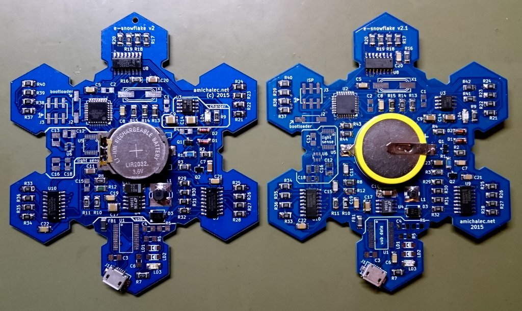
rev2 and rev2.1 boards
Planning next version let me fix 2.0 issues as well as rearrange pin assignments. The BUF_ENABLE line responsible for cutting of serial buffers, and effectively turning on/off the whole set of white lights, was moved to pin 13 so that PWM (using OC1A) could regulate relative brightness based on ambient light sensor input. This way global brightness is completely separated from logic responsible for dimming separate LEDs in animation sequences.
With that changes PCB was remade and files were rushed for production. They arrived 3 weeks later from China, and first board was assembled mid December 2015. Quick changes to firmware and revision 2.1 was ready.
Note that assemblies above are for “non electronic hobbyist”: no ISP connector and USB chip, no ambient light sensors (too expensive :P), no external crystal (higher power consumption).
Complete rev2.1 schematics below:
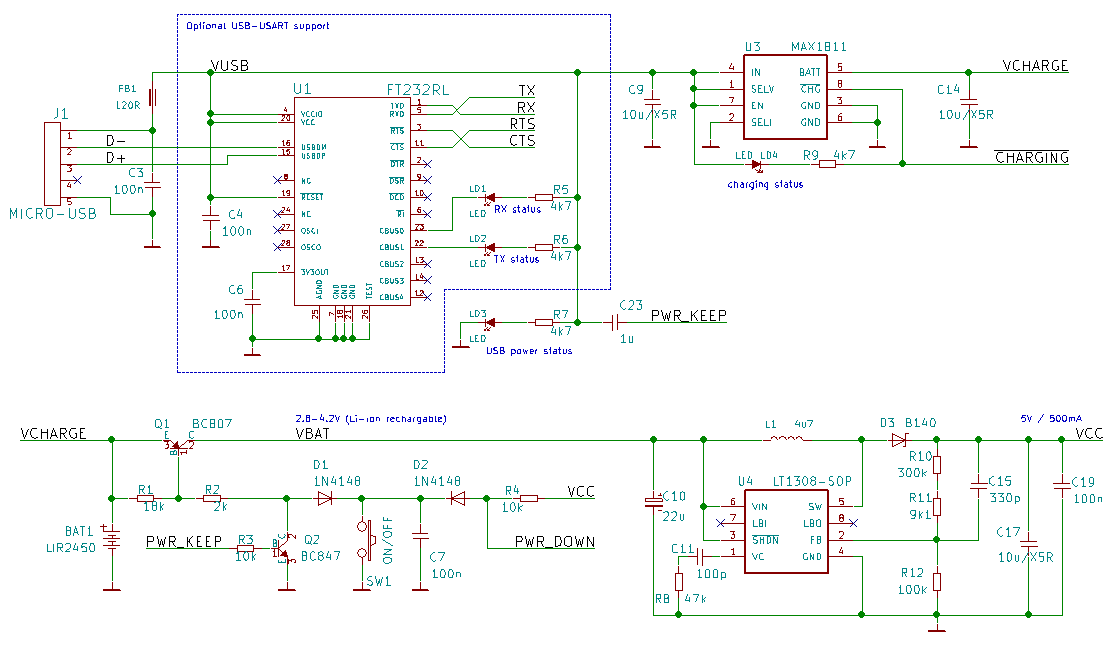
Power section
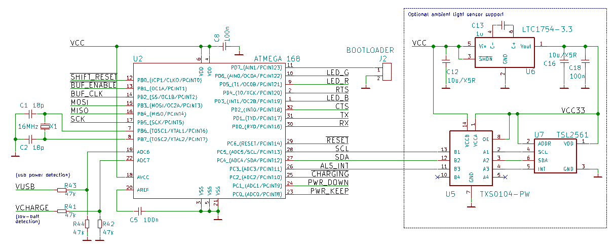
MCU and light sensor
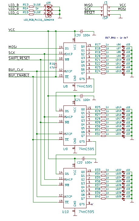
LEDs driver
Inherent imperfections

Terminator?
Despite I do not plan to make another iteration there is a room for simplification. Obviously 3.3V main supply voltage would serve better than 5V. It should be enough for most LEDs on the market and it is more typical voltage for ICs used. With that change LT1754-3.3 and TXS0104 could be removed. Despite 5V of USB FT232RL could have digital I/O pins configured to work to lower voltage (pin 4, VCCIO wired to 3.3V instead of 5V rail); that setup also would make PL2303HXD valid replacement for FTDI chip. To get down with output voltage in-between input voltage (2.8-4.2V) step-up converter had to be replaced with buck-boost converter; low-cost replacement for LT1308 would be either LTC3531 (tiny SOT23-6 case) or LTC3440 (MSOP-10).


