
Serial transmission over long line was the last stage of first iteration in prototyping. Local communication between microcontroller’s USART and PC was already working with MODBUS thus adding RS-485 driver and couple passive elements meant to be piece of cake. Murphy’s law got me down as I should have expected.
The idea is simple – from MCU perspective USART’s transmission lines RX/TX are connected to RS485 driver. Using simplest and cheapest half-duplex driver (one that allows at given time either send or receive data) extra line from microcontroller is required to specify direction of transmission – when “direction” line state is high it is sending data (Drive Enable pin) and when it is low it is receiving (negated Receive Enable pin). On the other end of RS-485 there are two differential signal lines A and B used for both sending and receiving – see drawing below.
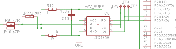
Driver lines A/B can be left alone and they will work in most cases, yet it is not good practice to leave them intact. In real-life conditions, transmission line introduces resistance plus it can induce noise, lowering differential voltage margin. Adding pull-up and pull-down resistors (R11/R12) counters this effect. Resistor R22 forms divider net with R11-R12 as well as it makes proper termination i.e. impedance matching to suppress reflections in high speed lines. Finally R9/R10 forms simple current limiters in case A/B lines are accidentally shorted.
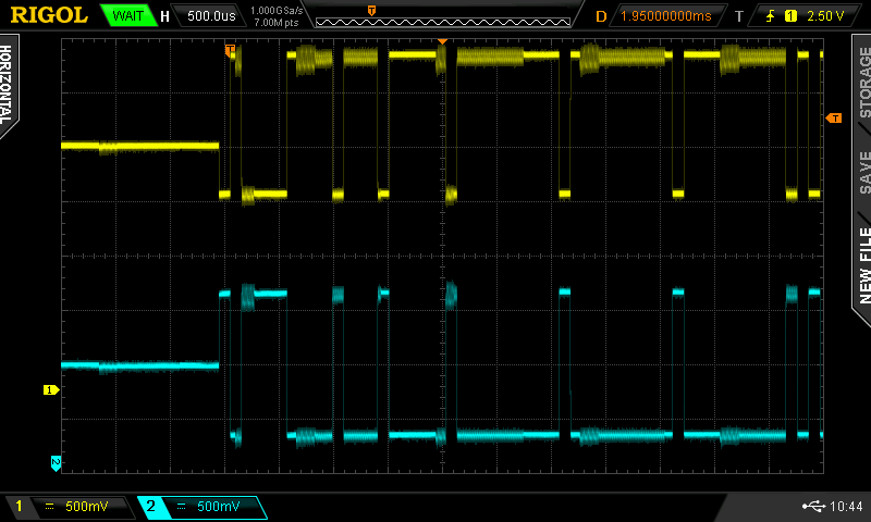
RS-485 waveform
RS-485 nature poses more problems in industrial environment – long lines and galvanic connections to separately powered ends introduces range of grounding problems, chassis voltage and unintended currents flowing between nodes – side effects with more severe consequences than noise and impedance mismatch. Isolated 485 transceivers can help out and some protocols (like PROFIBUS) demand use of them. They come at order of magnitude higher price – LTC485/MAX485 adds $1 to bill of materials, while isolated version like LTC1535 costs $15-20.
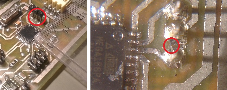
Shorted pins of RS-485 input
In my case the remote probe is powered from central unit, and the line does not exceed tens of meters, so it is still viable to use just a basic transceiver. Outdoor conditions like thunderbolts introduce other problems that require extra protection to the line itself, but I will talk about it separately.
Even though subsystem was simple, MAX485 was not working. I was struggling over an hour unable to diagnose the problem. Almost by accident I have discovered that TX and „direction” lines of MCU were giving the same signal, while they should not. Close inspection of PCB did not show shorts in traces. Even closer inspection shed new light – after dismounting plastic spacer of test-points pin header I discovered barely visible iron filing between two signal lines causing all the mess.
Once transmitter was ready I tested it with 30 meters line just to discover slight change in DC voltage signal due to cable resistance.
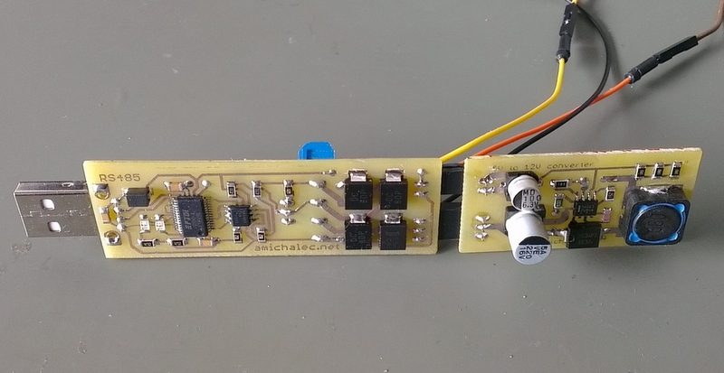
USB to RS-485 adapter with 12V generator
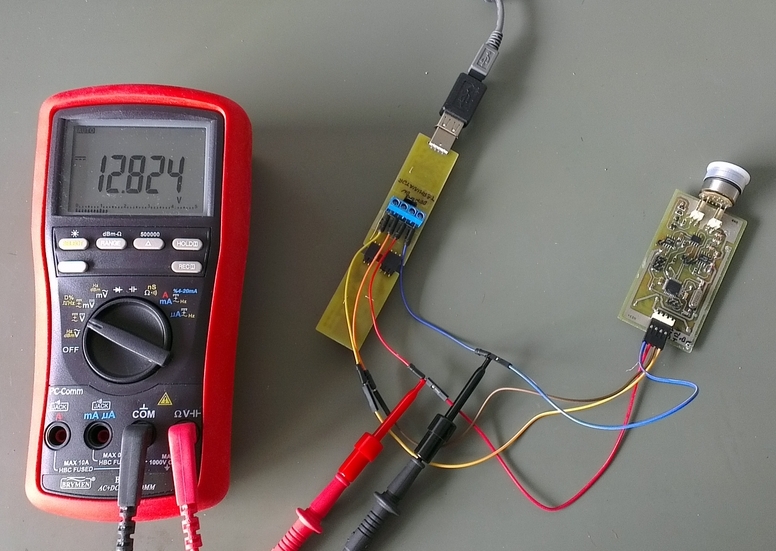
Laptop test for MODBUS/RS-485 probe
To make outdoor tests possible I have built USB to RS-485 converter based on FT232 chip. Since probe requires external 9V-15V power source I have designed it with detachable DC/DC converter based on MC34063 to turn 5V from USB into 12V supply, same voltage main unit will provide later. Equipped with laptop, converter and transmitter we made first successful field tests as shown on photos here
See also other related articles:
[posts_by_tag tag=”WLS”]


