Encouraged by successful RAM modification I started consider extension of USB ports number in TP-Link device. Originally it contains only one USB2.0 port and if you are using extroot (file system on external storage), you effectively have no free USB port. I was thinking about print server to share USB printer at home (printers with network cards are more expensive). I planned to have external HDD permanently attached to router case and I did not like idea of having another box, USB hub, with dangling wires.
The idea of USB mod is about building USB hub PCB into the router box. Steering lines of original USB port are cut off and redirected to hub as input. One of outputs is wired back to original USB socket, while other outputs are exposed through additional holes made up in the case.
I found that original USB port is powerful enough to spin off external HDD. I knew that some USB hubs are incapable of handling 0.8-1A of initial current, so I decided to buy active USB hub – if the electronics of hub is not capable of starting up the HDD, I have backup plan to power the hub from additional source. I bougth Unitek Y-206P as it is very slim, and will not make any problems fitting inside the hub.
I tested this USB hub before dismantling all hardware elements using pendrive, everything seemed to be fine (falsely as you will find later!).
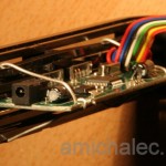
The best place to mount it is left side where inside elements do not interfere with additional PCB. The frame is made of tinny bars that form cooling crevices, and to make it stiff, these horizontal bars are connected in the middle with vertical bar. I did not want to rip off too big hole to mount additional USB ports and decided to expose only 2 ports on both sides o vertical bar. Cutting off one horizontal bar made a hole height of USB slot. Two additional silver wires worked as mounting racks stabilizing whole assembly when connecting/disconnecting USB plug.
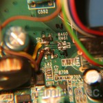
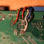
As I mentioned earlier, I wanted original USB port working as if unmodified. To do so, I had to inject hub between original USB lines on motherboard and original USB socket. I decided to use all 4 lines to hub, and another 4 lines back to USB socket. TX and RX lines are wired on top side. I made the least intrusive line break as possible by unbridging two SMT resistors R460 and R461; they were left on PCB for any future rollback of the modification. I needed to solder freely dangling cables to signal lines but I afraid to torn of very delicate PCB tracks, so I soldered wires to diodes’ pads.
On the bottom side I unbridged resistor R462. To isolate power lines (red wire) I needed to cut the PCB track, the only irreversible intervention.
Actually I could use only 4 lines (RX and TX there and back again) leaving Vcc and ground line untouched. I did that because I was not sure about possible interference of powering active USB hub with main board. The 8-line band has junction made of golden pins to make possible moving frame apart of other elements (well trained software desing principle in action). Finally all elements were put together fitting perfectly in tinny case.
To my surprise it stopped to work. All I got in log messages were hardware errors with different numbers. Googling revealed potentially damaged hardware. I could not believe I burnt USB hub because last run, couple hours earlier, was perfectly OK. I had to step back to find out where the failure is. Original port, wired back on 8-lines junction worked fine, so I was sure the problem lies within the hub. I did not see any signs of burn or short circuit so I started checking wiring. I suspected misplaced wires, either wrong TX/RX order, or even worse, mess up with power/ground lines. Multimeter test revealed short circuit between TX/RX hub input lines.
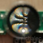
Thanks to watchmaker’s lens I could spot a microscopic ball of soldering matter that stuck between pins of USB host chip. I am not sure how this could happen, but optical instruments proved their necessity, not only working on SMT level.
Once the ball was removed, device started to work. The setup with external 4GB pendrive was stable and I could enjoy my craftwork for couple weeks. Problems started when I migrated system into ultimate hardware platform – router device with HDD in external case.
Here comes a little digression. I have seen hdd mods where disks are placed within the case. It is possible quite easy with 1,8″ disk. These storages are neither popular nor cheap. What is more, stuffing tiny box with another source of heat would lead to stability problems under heavy load. I was more liberal here and decided to stay with 2.5″ notebook HDD.
Right after moving to HDD storage I noticed that host chip started to get quite hot, even without much disk operations. Since I could still touch and keep finger on the chip I was ok with that. Problems started to appear after I begun loading the system with storage operations – copying large files, like 10-12GB, using FTP or samba was still fine. But starting transmission, the torrent client, led to system crush within 10-30 minutes. Investigation was long – I played a lot with different configurations, software versions, trying additional external power for active hub etc. without success. I shared my experience with other modders and the only conclusion was troublemaking USB hub.
I started hunting over. I needed an active hub with similar size and layout of ports (I already made holes in the case). First shot was complete misunderstanding, I got “USB2.0 hub” made in china for 1 euro, which worked stable but with speed of … USB1.1. Next one was Hama hub, made in germany. I have polaroid filter to my SLR made by Hama 🙂 so I decided follow the quality. I was lucky it worked fine whole night under heavy load, wired outside the box. After this test I managed to replace failing hub.
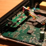
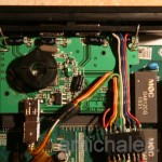
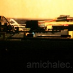
First problem was that PCB of Hama was twice higher than previous one, reaching further inside the case. To fit it well I had to saw off part of PCB, fortunatelly the area with ground tracks only. I had to double check proper placing of such a big PBC – if covers partially RTL network chip, which also is heating up one heavy data transfers. The placement of PCB of the hub lefe some place for airflow, visible on side view. This time I have also decided not to remove miniUSB socket and connect it to mutliwire tape. With previous hub I solder wires to dense tracks and I had to pin them down tighlty, not to accidenally tear off tracks from PCB with heavy cables. I have also left cooling radiator attached with adhesive thermoconductive tape.
With the hardware under tests I noticed that central unit is also heating a lot, when load was heavy and long. WordPress/mysql and other resource consuming service make this situation more typical, not only for stress tests. I decided to help here a bit too, sticking big fanless radiator from PC’s motherboard.
To summarize, my sweet spot configuration is as follows:
- Hama USB hub (based on GL850G controller)
- HDD Samsung HM320HI
- External HDD case “Carbon” with SPIF301-HL237 controller.
This setup is working for many weeks now, making no problems, and consuming two times less power than my PC in standby mode!
If you liked this article, help me to maintain blog on electronics and donate!
![]()

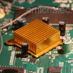



You should onnect the cooling plate which was glued to the cpu to ground by adding a wire whih is screwed on the cooling plate (aluminium) and solder the other end on shortest track to ground (look for a big ceramic capacitor and measure which side is ground).
This reduces transmitted EMI a lot.
Good point, next time I have this box opened I will wire radiator up to chassis.
Hi,
can you send me the project to make this mod?
tks.
eapiauhy@hotmail.com
What project are you referring to? This article is the only receipt how to made you own HW modification, no additional materials attached…
Hello,
I have question, is it possible to connect usb hub outside with factory frimwere or need to be updated with DD-WRT in order for usb hub to work.
Thank
Sure you can use external hub. If USB device connected to hub needs a lot of power (like HDD or 3G modem) then hub must be active (with its own power supply). However I do not like dangling cables hence this mod. And I needed active hub so I also made up extra supply inside router case.
Hello, please what is the value of a resistor R316, fell to a hushed, thank you.
You should use kapton tape to not blow it by hot-air gun 😉 It is zero ohm, make a bridge from tin/wire and you are good to go.
Hi! I have a WR1043ND v2.1. I use it with a 2.5 inch USB HDD which draws a little bit more than 500 mAh when under load. It spins up fine and works normally, except during large copying operations. After 20-30 secs the HDD spins down and than up again. After that it works.
Is it ok, if I use a Y cable and plug the other end into a power supply or could it damage the router’s USB port? Most powered USB-hubs backfeed power to the host port as well. Is it safe?
You have 2 safe choices – active hub between router and HDD (this is what I have done as a mod) or use HDD enclosure that has extra DC port for external power supply. Second option is darn cheap if you look around and find USB 2.0 chinese HDD cases.
Adding power supply to USB Vcc line is connecting two DC suplies outputs in parallel – some specific power supplies are designed to work in such topology, most are not. It may work initially when both have the same voltage but you need to think ofboundary cases: when one supply is turned off then backcurrent flows thru and if power supply is not designed to hadle it, prepare for rework of burnt parts 🙂 Since I hacked it quite a while ago and never done any serious reverse engineering of DC supply block, I assume it cannot work this way. Hence I do not recommend using Y cable directly.
Thanks. And what’s about backfeeding from the active USB HUB? A lot of HUBs do that… Don’t they connect the power lines as well?
Huh, other sources say active USB hubs usually dont 🙂 If they do it is probably misalignment with specs. I never tried mine hub from that angle. Even if it does backfeed I do not care that much, my hub is powered from 12V rail in router so parallelized DC-supplies start and stop almost at the same time and work on the same voltage and so far 3rd year without any problems…
Hello…
Firstly I would just like to say that you have done amazing work on 1043nd and since you have extensive HW working knowledge of the 1043nd may be you could help solve a problem everyone is facing.
Over years of usage wifi begins to drop signals and stop. Only way to get it to work again is to restart the router. Using Openwrt/DD-wrt. Could this be cause of failing power supply unit? As it’s rated at 1.5A and routers draws 1.5A(?) as well? So less power might cause wifi to malfunction?
I fixed my problem buy forcing router to run at 100T base full – duplex (this fixed high ping issue) and decreasing transmit power to 10mW. It’s stable of far. I am thinking of buying a 12v 3A power supply, hoping it might solve this problem. Your thoughts?
Is there a power draw limit set by router power block? If we add higher Amp power supply could USB then be used to power HDDs / charge phones / game controllers ?
Looking forward to your reply!
Thank you ^^
Tenrai, my insight is limited to areas I needed to hack. So I cannot tell why wifi is really degrading in you case – my guts feeling it is more related to software that hardware as I am running OpenWRT on this router for 4 years now without any changes (except rare system reflashing for update). Have you tried to clean OS (factory reset) or flashing different firmware to prove it is not software/driver issue? Do you use extroot and R/W filesystem? Does you wifi uses dynamic channels or static channel – this is relevant to older OpenWRT and WiFi-N that had drivers limit and unable to dynamically change channels; so you may have neighbour on the same channel interfering with your router.
As of you last question – no, adding higher amp supply will not increase built-in USB amperage, this is second part of my disertation in this article where I have added active USB hub inside to overpass 0.5A limit.
Finally you need to apply “divide and conquer” anyway. You can start with replacing power unit and observe. Then you should also check clean install of firmware and so on…